Introduction: Understanding the Heart of Every Electronic Device
Have you ever opened up a smartphone, laptop, or medical device and wondered about the intricate green board covered with tiny parts? Those components are the lifeblood of modern electronics. PCBA components, or Printed Circuit Board Assembly components, are the individual electronic parts mounted and soldered onto a PCB to create a functional circuit assembly. Think of them as the organs in a body—each with a specialized role, working together to bring an electronic product to life.
This comprehensive guide is designed for electronics designers, procurement specialists, engineers, and enthusiasts. You will gain a clear framework for understanding all key PCBA components, learn how they function, and discover practical strategies for selection and sourcing. By the end, you’ll be equipped to make informed decisions for your next electronic project or product.
Part 1: PCBA Component Fundamentals
1.1 What Exactly Are PCBA Components?
PCBA components are the physical, solderable electronic elements that populate a printed circuit board (PCB). They are not the board itself, but the parts attached to it. The process of attaching these parts is called PCB assembly, resulting in a complete PCBA.
Key Takeaway: A bare PCB is just a platform; it’s the components that enable electronic functionality.
1.2 Active vs. Passive: The Two Main Classifications
Understanding this fundamental split is crucial:
- Active Components: These can control the flow of electricity and typically require a power source to operate. They can amplify signals, switch currents, or process data. Examples: Integrated Circuits (ICs), transistors, LEDs.
- Passive Components: These cannot control current by means of another electrical signal. They primarily resist, store, or filter energy. Examples: Resistors, capacitors, inductors.
1.3 The Critical Functions of PCBA Components
Components serve four primary purposes on a board:
- Circuit Functionality: Creating paths for current to perform tasks (e.g., amplifying audio).
- Signal Processing: Modifying electronic signals (filtering, converting, timing).
- Power Management: Regulating, converting, and distributing power throughout the system.
- User Interface & Connectivity: Enabling interaction (buttons, displays) and connection to other devices (ports, connectors).
Part 2: The 7 Major Categories of PCBA Components (In-Depth)
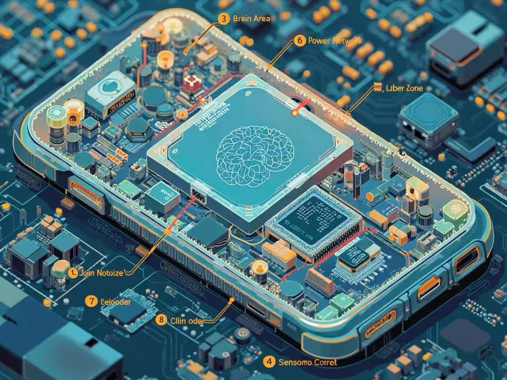
2.1 Integrated Circuits (ICs) – The “Brain”
ICs are miniaturized networks of electronic components (transistors, resistors) fabricated onto a single semiconductor chip.
- Types:
- Microprocessors (µP) & Microcontrollers (µC): The central processing units.
- Memory ICs: RAM (temporary storage), ROM/Flash (permanent storage).
- Logic ICs & ASICs: Perform specific logic operations or custom functions.
- Analog ICs: Amplifiers, voltage regulators, data converters.
- Selection Guide: Focus on package type (e.g., QFP, BGA), power consumption, clock speed, I/O count, and thermal requirements. Always check the manufacturer’s datasheet.
2.2 Passive Components – The “Support System”
These are the most numerous parts on a typical board, providing foundational electrical characteristics.
- Resistors: Limit current flow and divide voltages. Types: Fixed, variable (potentiometers). Key specs: Resistance (Ohms), power rating (Watts), tolerance.
- Capacitors: Store and release electrical energy. Used for filtering, decoupling, and timing. Types: Ceramic (common), Electrolytic (high capacitance), Tantalum (stable). Key specs: Capacitance (Farads), voltage rating, equivalent series resistance (ESR).
- Inductors & Transformers: Store energy in a magnetic field. Used in power supplies and filtering. Key specs: Inductance (Henries), current rating.
2.3 Connectors & Sockets – The “Joints”
These provide removable interfaces for power, data, and expansion.
- Types:
- Board-to-Board: Connects two PCBs directly.
- Wire-to-Board/Cable Connectors: Links internal or external cables.
- I/O Ports: USB, HDMI, Ethernet, audio jacks for user connection.
- Selection Guide: Prioritize current rating, durability (mating cycles), locking mechanism, pin count, and footprint.
2.4 Discrete Semiconductors – The “Switches & Diodes”
Individual semiconductor devices that perform core electronic functions.
- Diodes: Allow current flow in one direction. Types: Rectifier, Zener (voltage regulation), LED (light emission).
- Transistors: Amplify or switch electronic signals. Types: BJT, MOSFET (very common in power switching).
- Optocouplers: Isolate circuits electrically while transmitting signals via light.
- Selection Guide: For diodes, check forward voltage and max current. For transistors, check voltage/current ratings, switching speed, and gain.
2.5 Electromechanical Components – The “Actuators”
Components that involve both electrical operation and mechanical movement.
- Relays: Electrically operated switches.
- Switches & Buttons: Manual user input devices.
- Fans & Motors: Provide cooling or motion.
- Selection Guide: Consider mechanical life (cycles), drive current/voltage, switching speed, and physical dimensions.
2.6 Sensors & Transducers – The “Senses”
Convert real-world physical phenomena into electrical signals.
- Types: Temperature, humidity, pressure, motion (accelerometer/gyroscope), light, acoustic.
- Selection Guide: Focus on sensitivity, accuracy, output type (digital I2C/SPI or analog), power needs, and calibration requirements.
2.7 Power Components – The “Heart”
Manage, convert, and protect the board’s power supply.
- Voltage Regulators: Maintain a constant output voltage (Linear vs. Switching).
- Power Management ICs (PMICs): Complex ICs for multi-rail power control.
- Fuses & Protection Devices: Safeguard against overcurrent, ESD, and surges.
- Selection Guide: Efficiency is critical, especially for battery devices. Also consider thermal performance, output noise, and protection features.
Part 3: Technical Deep Dive: Specs & Packaging
3.1 How to Read a Component Datasheet
The datasheet is your ultimate guide. Key sections:
- Absolute Maximum Ratings: Never-exceed limits.
- Electrical Characteristics: Performance under specified conditions.
- Typical Application Circuit: How the manufacturer intends it to be used.
- Package Dimensions: Critical for PCB layout.
3.2 Component Packaging Formats
- Through-Hole Technology (THT): Leads inserted into drilled holes. Robust, easier for manual prototyping.
- Surface-Mount Technology (SMT): Components placed on pads on the board surface. Dominant in modern manufacturing; allows for smaller, denser boards.
- Common SMT Package Names: 0201, 0402 (size codes for passives), SOIC, QFN, BGA (for ICs).
Part 4: Practical Selection & Procurement Guide
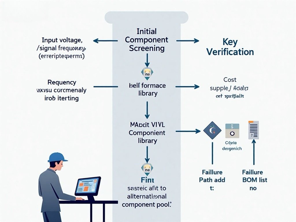
4.1 The 5 Principles of Smart Component Selection
- Function & Performance: Does it meet all technical specs with margin?
- Supply Chain & Availability: Is it in stock at major distributors? Is it at risk of obsolescence?
- Cost vs. Performance: Is a cheaper alternative sufficient? Avoid over-engineering.
- Quality & Reliability: Does it have necessary certifications (AEC-Q100 for automotive)? What is its MTBF (Mean Time Between Failures)?
- Manufacturability & Layout: Does the package fit your PCB design rules? Is it compatible with your assembly house’s capabilities?
4.2 Avoiding Common Selection Pitfalls
- Pitfall: Ignoring operating temperature range.
- Fix: Always select components rated for your product’s worst-case environment.
- Pitfall: Choosing a component nearing “End-of-Life” (EOL).
- Fix: Check manufacturer lifecycle status and plan for second sources or replacements.
- Pitfall: Overlooking decoupling capacitor requirements for ICs.
- Fix: Follow the IC datasheet’s PCB layout recommendations precisely.
4.3 Managing Your Supply Chain
- Use Authorized Distributors: For guaranteed authenticity and warranty.
- Qualify Alternate Sources: Identify second-source components during design to mitigate risk.
- Plan for Long Lead Times: For critical components, forecast early and consider inventory buffers.
Part 5: Frequently Asked Questions (FAQ)
Q1: What is the smallest PCBA component size?
A: Standard mass-produced SMT passives (resistors/capacitors) go down to 01005 package (0.4mm x 0.2mm). Advanced packaging like chip-scale packages (CSP) for ICs are even smaller.
Q2: How do I know if a component is compatible with my design?
A: Cross-check three things: 1) Electrical specs (voltage, current, speed), 2) Physical footprint on your PCB layout, and 3) Availability for prototyping/production.
Q3: What is the typical lifespan of PCBA components?
A: Lifespan varies widely. High-quality passives can last 20+ years. ICs and electromechanical parts (relays, fans) often have shorter operational lives. Always refer to the component’s predicted failure rate (FIT) or lifetime specs in the datasheet.
Q4: What’s the difference between commercial, industrial, and military-grade components?
A: The primary difference is the operating temperature range and testing/reliability standards. Commercial (0°C to 70°C), Industrial (-40°C to 85°C), Military (-55°C to 125°C with stricter testing).
Q5: How should I respond to a component End-of-Life (EOL) notice?
A: Act immediately. Options include: 1) Last-Time Buy, 2) Finding an approved alternative, 3) Redesigning the circuit section, or 4) Using a franchised distributor’s lifecycle management service.
Conclusion and Next Steps
PCBA components are the fundamental building blocks that translate a schematic diagram into a working electronic product. Success hinges on understanding their roles, specifications, and the practical realities of sourcing and manufacturing.
To proceed effectively:
- For Beginners: Start with a popular development board (like Arduino or Raspberry Pi) and study its Bill of Materials (BOM).
- For Professionals: Implement a Component Management Strategy early in your design process, focusing on lifecycle, alternates, and supply chain risk.
- For Everyone: Build a relationship with a reputable PCBA contract manufacturer (CM). Their expertise in Design for Manufacturability (DFM) and component sourcing is invaluable.
By mastering the knowledge in this guide, you move from simply seeing a complex board to understanding it—empowering you to design, troubleshoot, and procure with confidence.
Ready to turn your design into reality? Begin by auditing your next BOM against the selection principles outlined here. For further learning, explore resources from component manufacturers like Texas Instruments, Analog Devices, and Murata, which offer extensive application notes and design tools.